| Construction begins! From the ground up, of course. The base boards that I had measured up from design 3.7, and materials procured during the construction phase started to come together. As always with youthful exuberance, a steady hand of wisdom to guide was a great help, and for that I had Dad (and his army of power tools) come around to give me a hand and get the majority of the work done. So let's start with the tools. | 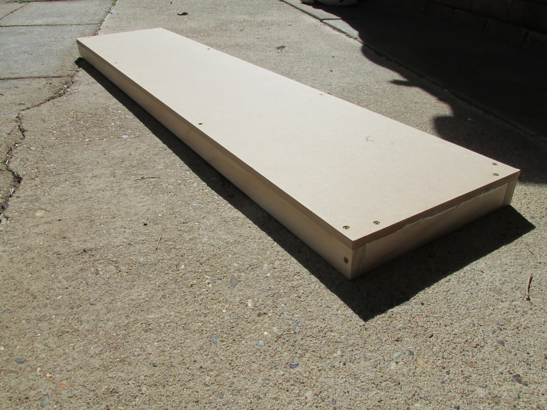 |
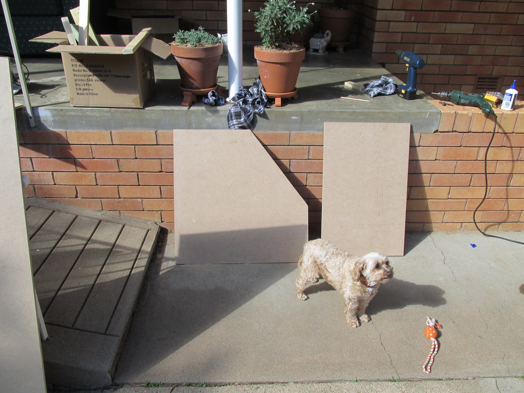
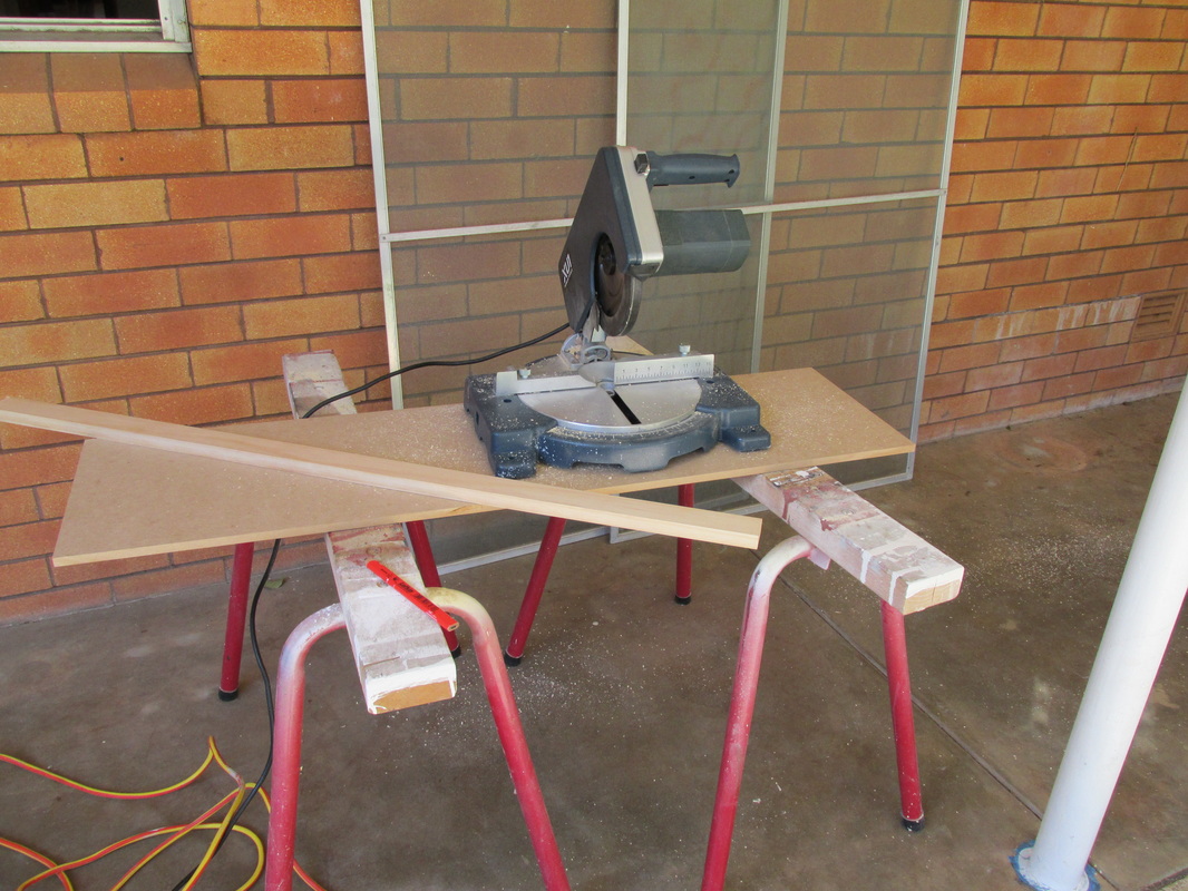 | We had 2 drills, one electric and one cordless rechargable, 2 drill bits (2.38mm drill bits, which can later be used to drill holes through the base board for wiring but I'm getting ahead of myself here), one screw driver head for the drills, a table mounted saw, a circular saw and a jig saw (which I am yet to use). Most importantly, a tape measure and pencil which every engineer is lost without. The 2 drills idea by dad was probable the most useful aspect of the tools we had. Materials needed to be bought included A 500mL tub of interior PVA glue and 200 Chip board screw (8Gx40mm, countersunk with phillips head drive). In total, and in addition to the materials procured |
| in the July budget, the total purchase (including drill bits and screw drive heads came to $31.77, which puts me just over the $200 per month budget by 77 cents! To get the ball rolling, we started with a simple rectangular piece, so we had the construction method sorted and understood the pattern. The method of construction was simple, measure and cut the lengths of the 3m long pine to the desired size of the long sides and then use these cut outs to gain the information about the short sides, and limit the use of the tape measure for this practice. This eliminates any discrepancies if the base board cuts were not square. | 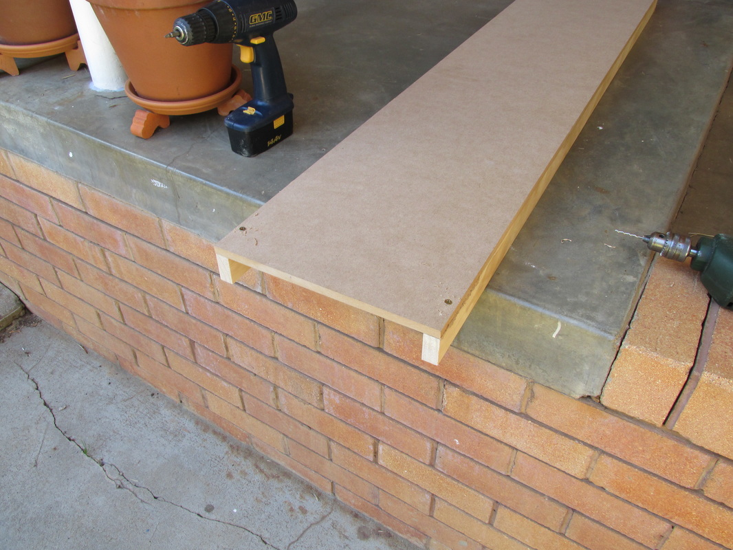 |
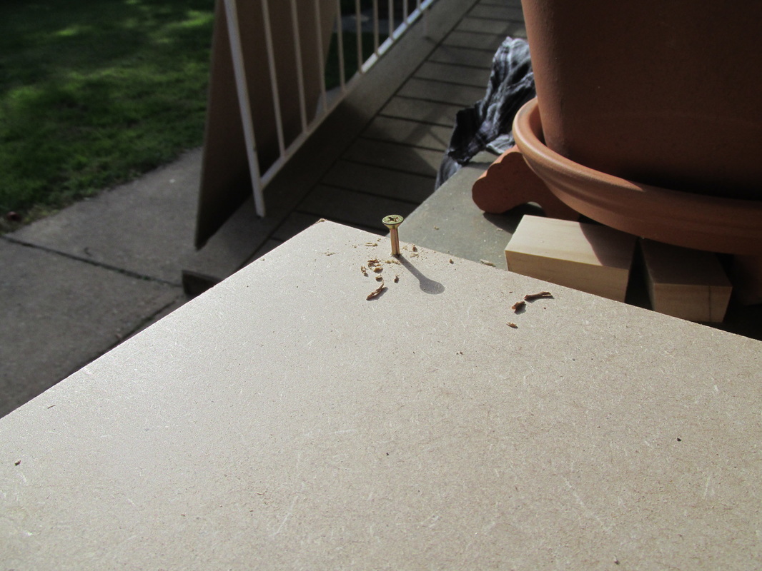 | We then put the drill bit into the electric drill, and the phillips head screw driver bit into the cordless drill. We then drilled a hole with the electric drill to where the screw would be placed. This was to limit the likelihood of the timber splitting, and out of some 150 screws, only one screw split the timber due to operator error on my part. When the screws went to be placed in then holes, we used the battery operated drill and left the screws about 8mm out of the timber. This was for 2 reasons; 1. It saved the battery on the rechargeable drill 2. The electric drill easily had more power to achieve the counter sunk effect required. |
| Once all screws were in this first piece we changed the heads and used the electric drill to screw the screws into the timber. This would in effect allow us to later in the day set up a production line of one person drilling, while the other screwed, and when enough (about 3 or 4) of the boards were done we would change the bits over and counter sink the screws. With most of the rectangular pieces done, the cutting of the oddly shaped pieces could now start (after a brief lunch break of course!). First we reset the work area ready to use the circular saw. | 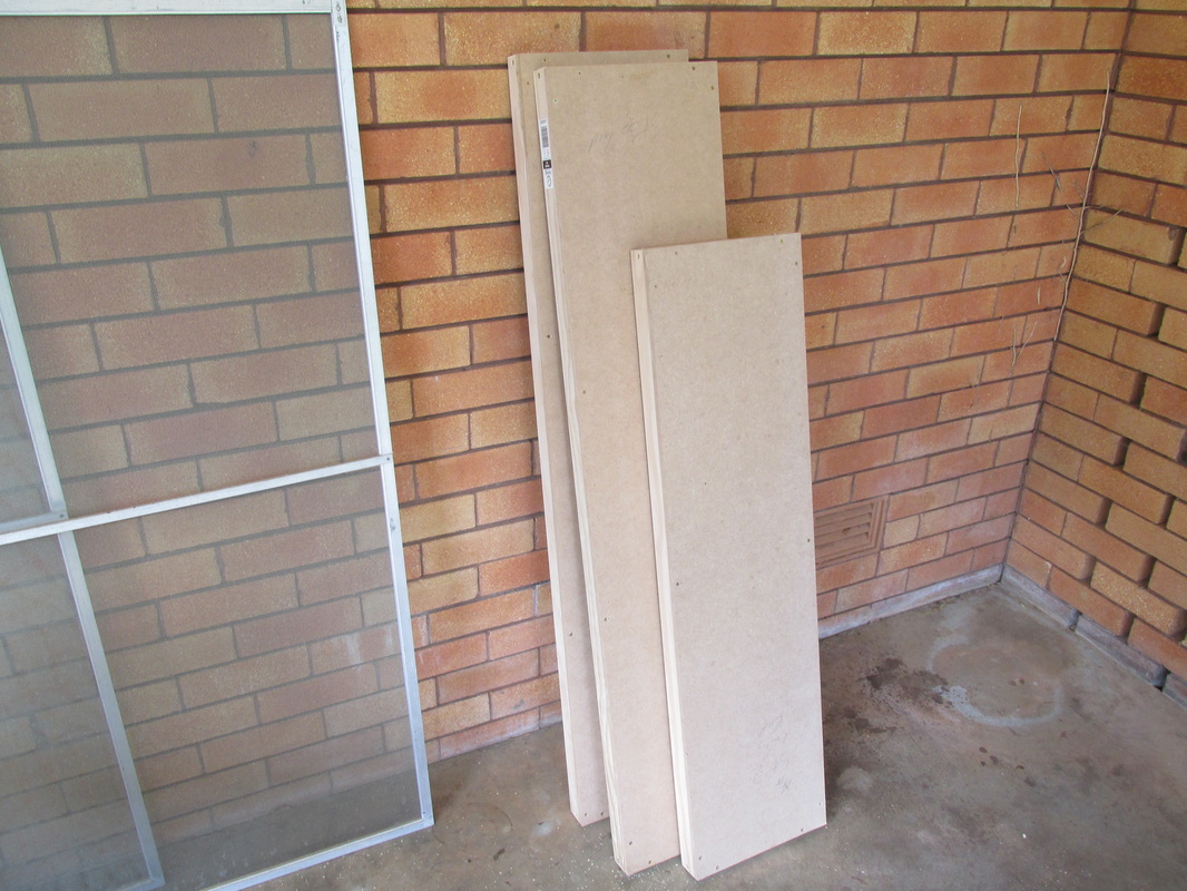 |
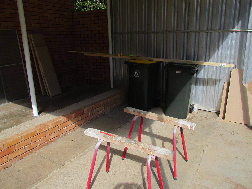 | We measured and drew on the pieces of board comparing with the laptop plan and the measurement. This went very smoothly, and we used the circular saw (free hand) to cut the pieces down to size. From these off cuts we were able to make some additional pieces as per the plan. It was then time to cut, drill and screw the pieces of pine and to the cut boards. This used the same method as before and of the 14 lengths of 3m pine, I had 2 left over (these will go into making the legs later on). |
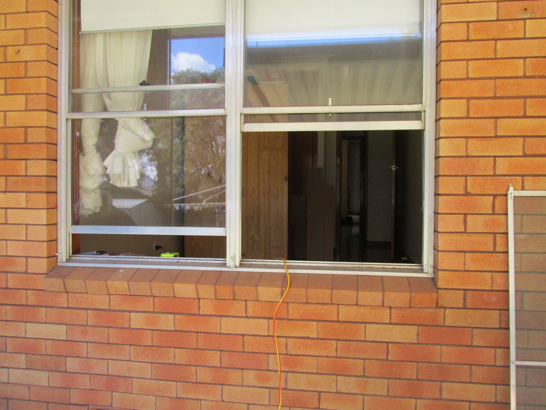
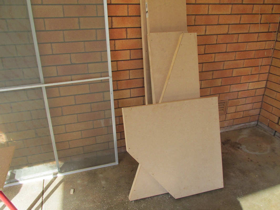
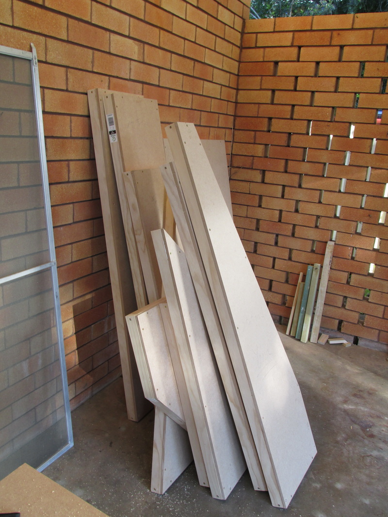
| Again this all went fairly smooth. The one near heart stopping moment was when we near screwed the pine to the wrong side of an asymmetric board which would have required a fair bit of work to fix. Luckily we caught it after we drilled the hole, but before we screwed the screw in. Apart from the near heart attack this caused, it all went together very well. We took the fly screens off the window (seen in some of the photos) and opened the windows to pass the finished pieces through. After afternoon tea, a quick clean up, and fare-welling Dad, my girlfriend and I set the pieces on the floor. Do you want the good news, or the bad news? | 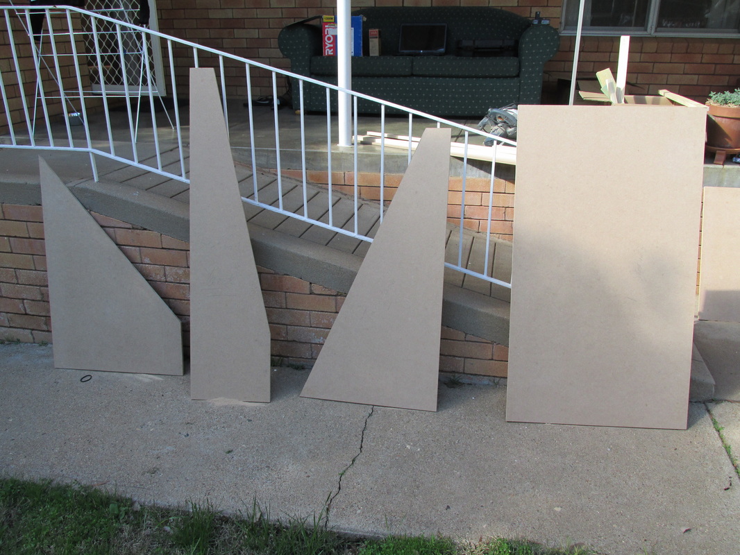 |
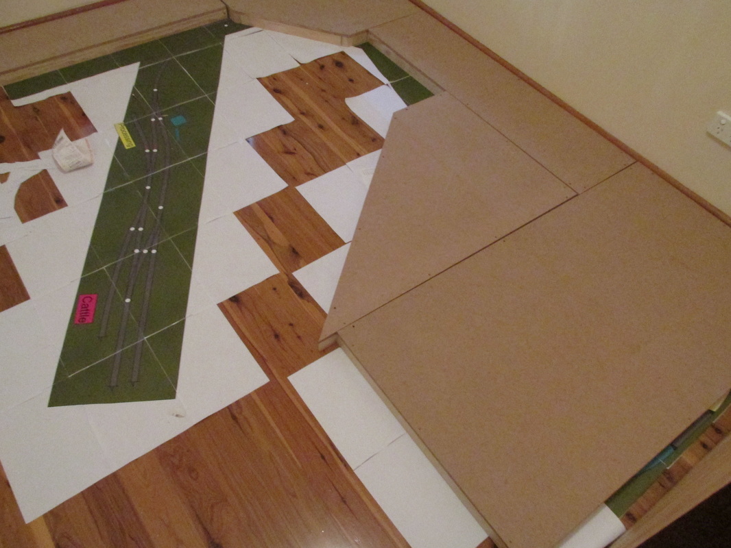
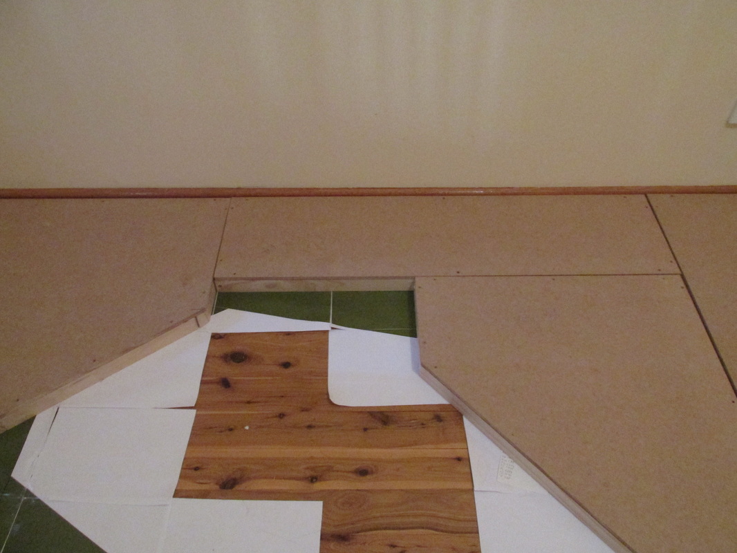
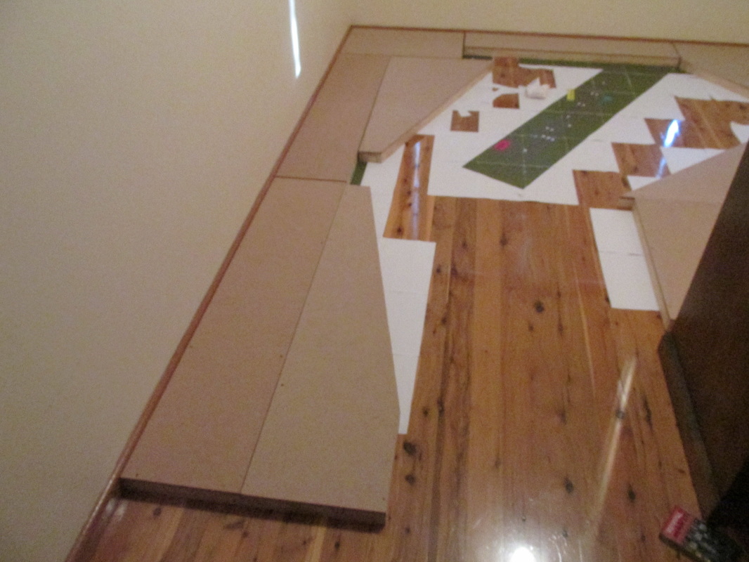
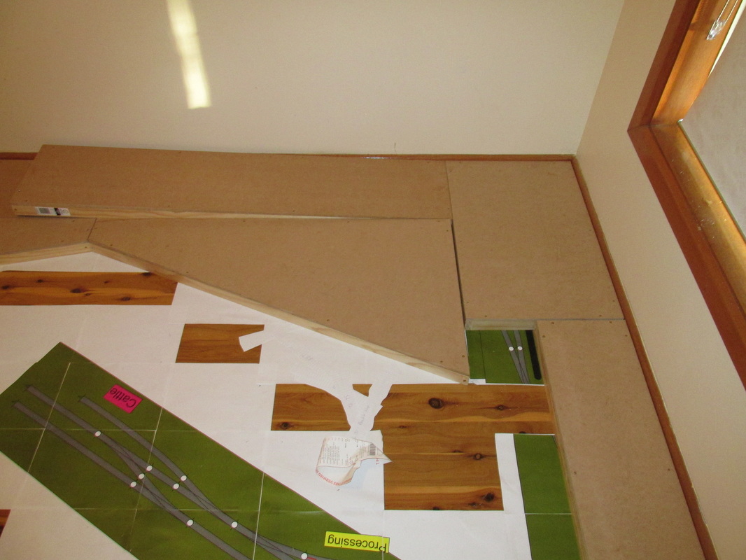 | I'll start with the bad news as it has a silver lining. As you can see in the picture to the left, we have a mis-measure. This piece is about 200mm too long. A mistake on my part. Towards the righ side of the picture you can see that the base board actually comes a bit short.... Well yes and no. Yes because the board should have been 300mm not 250mm, but this has a silver lining, as the centre piece depicted in green on the floor will sit between 20 and 30mm lower than this base board. So it's actually worked out well. Now let's look at the overhang. |
| As you can see, there's actually plenty of room. The silver lining here is that I've gained 20mm that I didn't have before! Time for a quick redesign? I THINK SO!  | 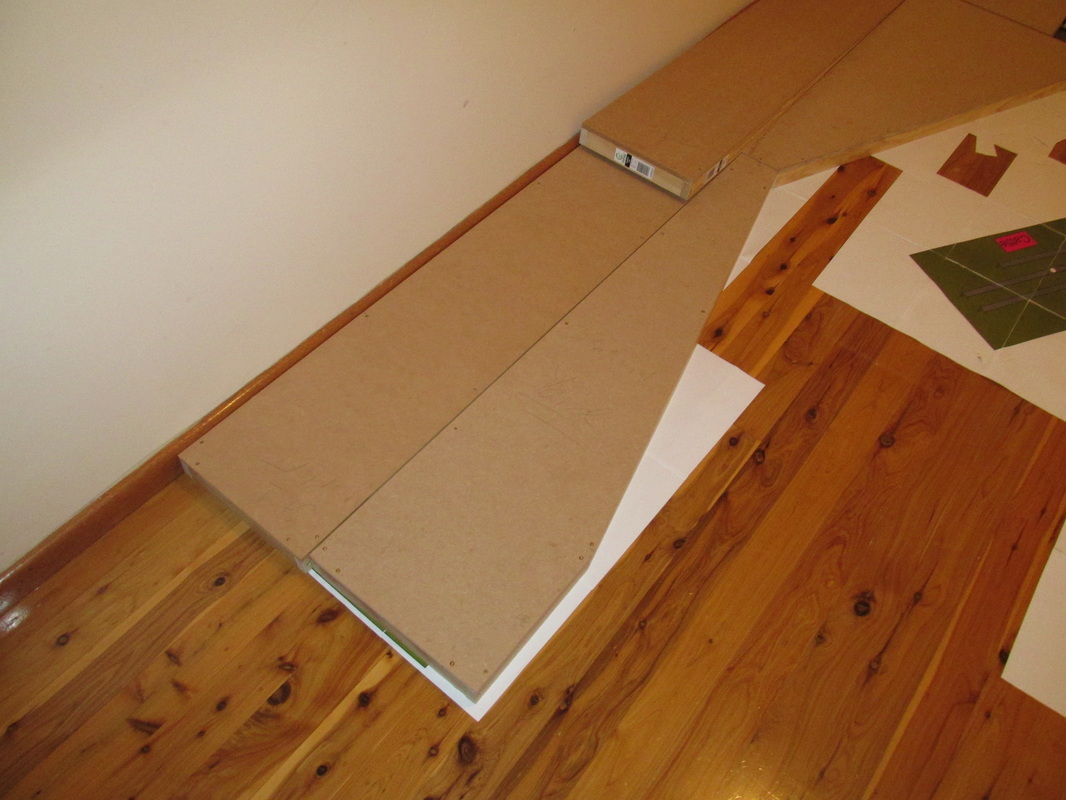 Did anything else go wrong? Well yes, one triangular piece may have been measured wrong (or I mixed up the lengths of a few pieces, I'm not too sure and don't particularly wish to find out). |
| This should be an easy fix with the circular saw as there are no screws on the ends. So the good news. I gained some space in the yard at station 1, most of the pieces went together as planned. The only spots where the paper showed through are where the base board design called for a fill in piece (of which I have plenty!). it's all coming together quiet well. It's looking more and more like a railway room each weekend! Below is a gallery of some of the pictures I took of the process that didn't make it into the blog. | 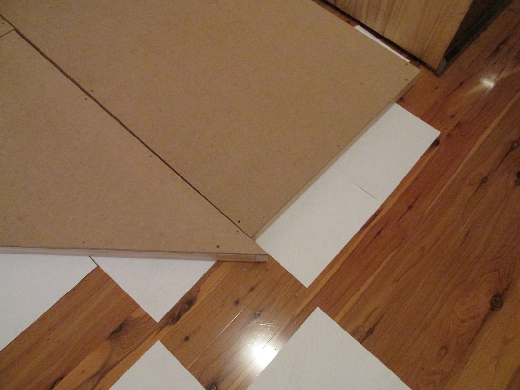 |
But first, what's next? Well probably 2 design blogs. 1 for the legs of the base board, and 1 for the resdesign with the additional room. And then we'll look into the legs. Also I'll need to paint and putty the base boards. Then we can start laying track and playing with a few ideas!


 RSS Feed
